
How industry mentorship and learning led to a summer of design
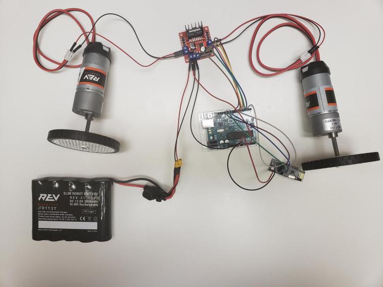
The electronics inside the robot.
My name is Chad Ronish, and as an engineering student, I love to design and create things. However, while I’m excellent at Computer-Aided Design (CAD) and 3D printing, before this summer, I felt less confident in coding and electronics.
During summer 2020 and the unfolding of a global pandemic, I was given the opportunity to take part in the ME Summer Design Intensive organized by CU Boulder’s Paul M. Rady Department of Mechanical Engineering, a program in which practicing engineers and recent graduates guided students through the development of personal design projects. I knew this was a great opportunity to take a project from the idea stage, design it, and fabricate a prototype, as I had both peer and industry mentors to help me figure out things like the electronics and coding.
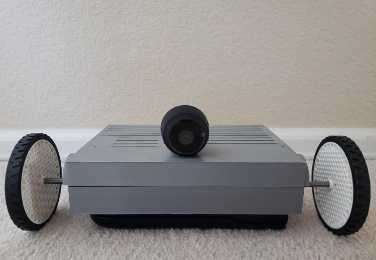
The assembled robot.
I settled on the idea of a robot that would send real-time video footage of its field of view to the controller, with the objective being to design and prototype a robot-controlled wirelessly through radio frequency. An operator would use a handheld controller that sends commands to the robot, while the robot would simultaneously send a live video feed to the operator via a wireless camera.
This project required custom CAD for the base of the robot and the shell of the controller, research into electronics and a custom circuit design, and complex coding to allow for wireless communication between the controller and the robot. Everything for this project was built from scratch or some premanufactured parts, and at no point were other similar products used for this project.
To start out, I needed to do a lot of research into the electronics I would need for this project to function. It took some time, as I have never really done something this in-depth electronically, and I needed to figure out how to take two motors and control both speed and direction of rotation. This was solved with an L298n H-Bridge, which worked not only to control the direction of rotation of DC motors but also to control the speed of the motors using pulse width modulation.
The next challenge was finding a radio frequency communication device and figuring out how to connect it to a microcontroller. I found an nRF24L01 radio frequency transceiver which worked well because it came with a breakout board and guidelines for simple connection to the Arduino, as well as lots of online resources for the coding.
From the research I did and the assistance I gained from my industry mentor from the program, it turned out that the electronics were much simpler than I anticipated. But the coding was still challenging. I investigated online forums that discussed the nRF24L01 and how to program it. Though coding in pulse width modulation to control the direction and speed of the motors through the H-Bridge was relatively simple, combining the two proved even more difficult. Coding the controller to send out the data that is needed to do pulse width modulation from the joysticks to the robot and then getting the robot to understand the data and transfer it into commands was very challenging. It took time and a lot of online resources, but I was eventually able to code things in a way that allowed them to function the way I wanted.
To any future students looking to do something like this, I would recommend doing some research online as there are many useful resources available that can help inspire you or help answer a problem or question you had. A lot of time was spent researching how to set up code that would allow radio frequency communications between two Arduinos and the electronic hardware needed. There were many online resources that allowed me to get a better idea of what to do and how to do it. Even if you don’t know how to do something, don’t give up on it. See if you can find resources that will help explain it, help work on it and allow you to approach the problem better.