
How I built an electric bicycle
My name is Xander Sugarman, and I am a mechanical engineering student passionate about having fun on bicycles. I have always wanted an e-bike; however, they tend to be quite expensive, which is a major barrier to entry. After my summer internship was cancelled due to the pandemic, I applied to the ME Summer Design Intensive in hope of getting some of the experience that I would have in my internship. This was an excellent opportunity to do a personal project with some help from industry professionals. After some thought, I decided this was the perfect opportunity to design and build my own e-bike!
My plan was to start with a regular bicycle, then design and manufacture all of the components to incorporate a battery and an electric motor to provide extra power. The first challenge was to find a good bike that would be a blank canvas for the project. I ended up finding a perfect solution on Craigslist. The bike I chose was a rigid, single speed, steel frame mountain bike with hydraulic disc brakes. This was perfect because the mountain bike geometry would make for a stable ride, and the hydraulic disc brakes would provide enough stopping power, which would be needed for the high speeds I would be designing for.
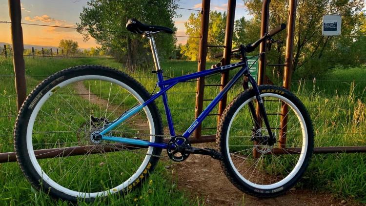
Above: GT Peace 9R
Next, it was time to take measurements and start CAD to design all of the parts to fit inside the bike. I split the design into two subassemblies: front drive and rear drive. The front drive fits inside the triangle right above the bottom bracket. It will also be relatively heavy, so mounting it lower, right over the bottom bracket, will keep the bike's center of mass in an ideal location. The front drive contains a plate that mounts the motor, two pulleys, and a sprocket that connects a chain to the rear drive. The plate is machined out of 6061 T6 aluminum. The small pulley came with the motor, and the large pulley is 3D-printed steel (thanks to Desktop Metal!) With the smaller pulley, it gives a gear ratio of 1:3. The plate is mounted to the frame in two locations, and the mounts are 3D-printed PETG. The sprocket is a 19-tooth #25 steel sprocket.
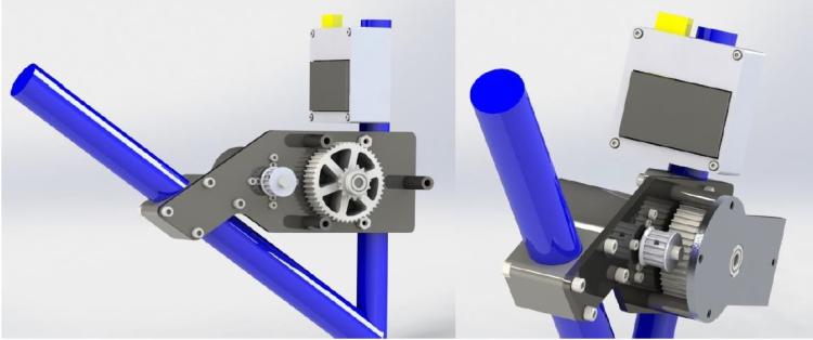
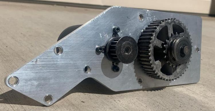
Above: Rendering of front drive and controller case. Below: Motor bracket with mounted motor and pulleys
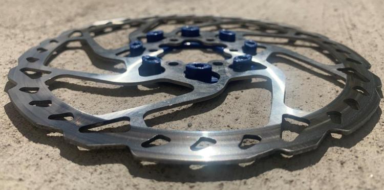
The rear drive is mounted directly to the rear wheel using the 6-hole disc brake mount. A challenge with the rear drive was that the bike needed a large sprocket to provide an optimal gear ratio from the motor to the rear wheel. I ended up needing a 120-tooth sprocket for this. Along with the two pulleys in the front drive, the total motor to rear sprocket gear ratio is about 1:19. I used two plates to fit the massive sprocket, one on each side of the rotor to mount my components to the rear wheel. Connected to the inner plate are six spokes that bend around the brake caliper, which the sprocket connects to. The outer plate is currently 3D printed PETG. I hope to replace this with an aluminum machined version but have not yet. The inner plate is machined 6061 T6, and the sprocket is machined stainless steel. The outer ring around the sprocket is a PETG 3D printed chain guide to correct for the chain misalignment between the front and rear drive. The 6 spokes are aluminum sheet metal.
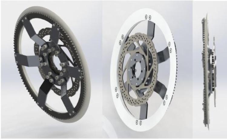
Above: Rendering of rear drive. Below: Outer plate protrudes through spaces in the rotor allowing it to attach to the inner plate.
The third part of this project was selecting the electronic components. The motor is a 6384 BLDC motor, with a max rated power of 4000 watts. The battery powering the operation is a massive 30 Ah, 48V lithium ion capable of a continuous 50A (fully charged at 58.8V). The battery is mounted inside a plastic case on a rear wheel rack. The controller is a VESC6 motor controller, rated for 100A and 60V. The user controls a twist throttle, which supplies an analog input to the controller.
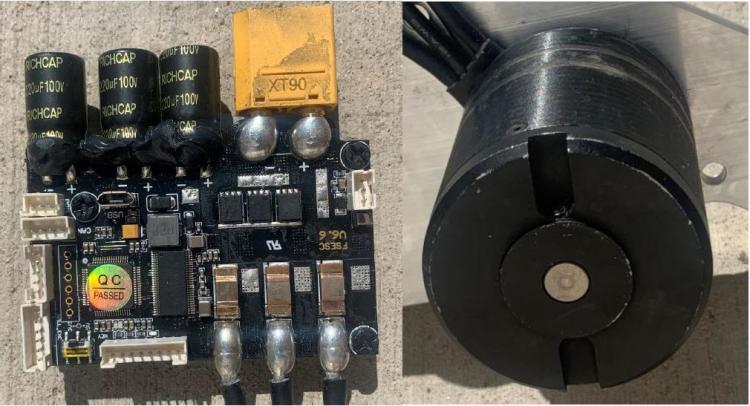
Above left: Controller. Above Right: Motor
The design took about four weeks during the CU Mechanical Engineering Summer Design Intensive, but sourcing all of the custom manufactured parts took about six months, and I still do not have all of the parts. However, I have enough of the bike to have an extremely well-functioning, super fun electric bicycle that I have been commuting basically everywhere on. The bike is very powerful compared to what a human can produce. With a max power of 3000 watts and a max speed of 37 mph, the power and acceleration make for quite the ride! It was a great time getting to do a personal project in an area I am interested in and coming away with a result that I can use all of the time. There are definitely a few changes I would implement if I were to make another prototype, but this one works great!
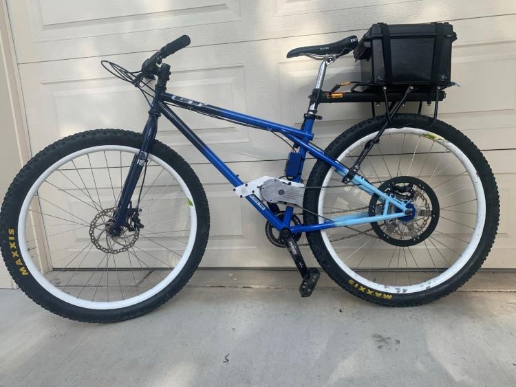
Above: Fully constructed e-bike.