
Resonant Converters
Modeling, analysis, and control of resonant converters
Basic research on traditional resonant converters.
- A. Witulski and R. Erickson, “Steady-State Analysis of the Series Resonant Converter,” IEEE Transactions on Aerospace and Electronic Systems", vol. AES-21, no. 6, pp. 791-799, November 1985.

Output characteristics of the series resonant converter, above resonance. Solid lines: normalized voltage M vs. current J. Dashed lines: normalized tank current JLP. Dotted lines: normalized tank capacitor voltage MCP.
This paper was the first to derive a closed-form exact solution of the series resonant converter with simple frequency control. The exact output characteristics in CCM were shown to be elliptical. - A. Witulski and R. Erickson, “Design of the Series Resonant Converter for Minimum Component Stress,” IEEE Transactions on Aerospace and Electronic Systems", vol. AES-22, no. 4, pp. 356-363, July 1986.
Closed-form solutions of component stresses are overlayed on the converter output characteristics, and the results are used to optimize the converter design. - S. Johnson and R. W. Erickson, "Steady-State Analysis and Design of the Parallel Resonant Converter," IEEE Power Electronics Specialists Conference, 1986 Record, pp. 154-165, June 1986.
This paper was the first to derive a closed-form solution of the parallel resonant converter with constant frequency control. Further details are included in Steve Johnson's M.S. thesis. - S. Johnson and R. W. Erickson, "Steady-State Analysis and Design of the Parallel Resonant Converter," IEEE Transactions on Power Electronics, Vol. 3, No. 4, pp. 93-104, Jan. 1988.
- S. Trabert and R. Erickson, “Steady-State Analysis of the Duty-Cycle Controlled Series Resonant Converter,” IEEE Power Electronics Specialists Conference, 1987 Record, pp. 545-556.
This paper introduces a general technique for analysis of resonant converters. State plane analysis of the tank waveforms during each subinterval reduces the analysis to geometry. Kirchoff's laws in integral form connect the average terminal waveforms to points on the state plane trajectory. In this paper, the approach is applied to analysis of a constant-frequency duty-cycle controlled series resonant converter. The complete analysis technique is explained in greater detail in Steve Trabert's M.S. thesis, 1987. - Arthur F. Witulski and Robert W. Erickson, "Small Signal AC Equivalent Circuit Modelling of the Series Resonant Converter," IEEE Power Electronics Specialists Conference, 1987 Record, pp. 693-704.
This paper introduces a small-signal y-parameter model for the series resonant converter, describes its physical interpretation, and predicts small-signal transfer functions. - Arthur Witulski, Adan Hernandez, and Robert Erickson, "Small-Signal Equivalent Circuit Modeling of Resonant Converters," IEEE Transactions on Power Electronics, January 1991.
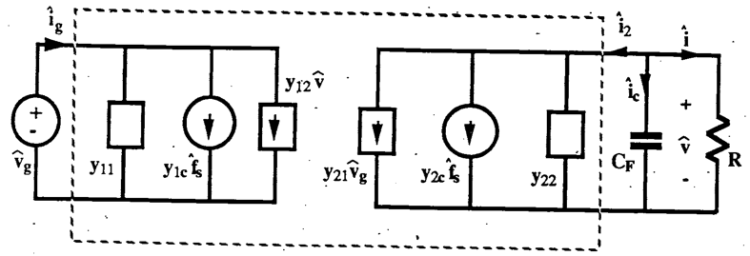
y-parameter model of the series resonant converter
This paper generalizes the small-signal ac modeling approach of the previous paper, and includes results for both the series- and parallel-resonant converters. - S. D. Johnson, A. F. Witulski, and R. W. Erickson, "A Comparison of Resonant Topologies in High Voltage Applications," IEEE Applied Power Electronics Conference, 1987 Proceedings, pp. 145-156.
Series, parallel, and LCC resonant converter topologies that incorporate transformer resonances in high-voltage dc applications. Extensive experimental results are presented. - S. D. Johnson, A. F. Witulski, and R. W. Erickson, "Comparison of Resonant Topologies in High Voltage Applications," IEEE Transactions on Aerospace and Electronic Systems, vol. 24, no. 3, pp. 263-274, May 1988.

Use of the high-voltage transformer resonant input impedance characteristic in a resonant dc-dc converter.
- A.F. Hernandez, R.W. Erickson, S. Lofton, and P. Anderson, “A Large Signal Computer Model for the Series Resonant Converter,” IEEE Power Electronics Specialists Conference, 1991 Record, pp. 737-744, June 1991.
A SABRE-based averaged model of the series resonant converter that employs state-plane analysis and Kirchoff's laws in integral form to achieve fast simulation of systems that include series resonant converters. - P.M. Anderson, S.E. Lofton, R.W. Erickson, A.F. Hernandez, and G.L. Fronista, “Requirements and Design of a 30 kW DC-DC Converter for Space-Based Radar Applications,” IEEE 26th Intersociety Energy Conversion Engineering Conference, vol. 2, pp. 184-189, 1991.
Design of a high-density series resonant converter for an aerospace application. - Y. Yin, R. Zane, J. Glaser, and R. Erickson, “Small-Signal Analysis of Frequency-Controlled Electronic Ballasts,” IEEE Transactions on Circuits and Systems, I: Fundamental Theory and Applications, special issue on switching and systems, vol. 50, no. 8, pp. 1103 – 1110, August 2003.
- Y. Yan, R. Zane, R. Erickson, and J. Glaser, “Dynamic Analysis of Frequency-Controlled Electronic Ballasts,“ IEEE Industry Applications Society Annual Meeting, October 2002.
This paper extends the phasor transformation method to permit small-signal modeling of resonant inverters when both frequency modulation and amplitude modulation are present. This is necessary to model the control dynamics of high-frequency resonant inverters in applications such as gas discharge lighting. - R. Erickson, "Resonant Power Conversion", tutorial seminar given at IEEE Power Electronics Society Denver chapter meeting, Oct. 2010 (and elsewhere). Downloadable slides included here for convenience of attendees.
Resonant switch converters
Several publications on resonant switch converters are listed below. See also the page on low-harmonic rectifiers for a number of publications involving resonant switch schemes in rectification applications.
- Robert Erickson, Adan Hernandez, Arthur Witulski, and Renjie Xu, “A Nonlinear Resonant Switch,” IEEE Transactions on Power Electronics, vol. 4, no. 2, pp. 242-252, April 1989.
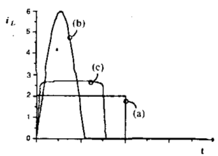
Comparison of transistor current waveforms: (a) ideal PWM, (b) quasi-resonant ZCS, (c) nonlinear resonant switch.
A biased saturating tank inductor is introduced into the ZCS resonant switch, to reduce peak currents and cause the transistor current to scale with load current. - Arthur Witulski and Robert Erickson, "Extension of State-Space Averaging to Resonant Switches and Beyond," IEEE Transactions on Power Electronics, vol. 5, no. 1, pp. 98-109, January 1990.
A proof of how state-space averaging can be applied to resonant switch converters and other converters, along with a general definition of the switch conversion ratio. - Arthur Witulski and Robert Erickson, "Extension of State-Space Averaging to Resonant Switches—and Beyond," IEEE Power Electronics Specialists Conference, 1989 Record.
- Yungtaek Jang and Robert Erickson, “New Quasi-Square Wave and Multi-Resonant Integrated Magnetic Zero Voltage Switching Converters,” IEEE Power Electronics Specialists Conference, 1993 Record, June 1993.
Both the tank inductor and the filter inductor are integrated into a single magnetic element. By proper coupling between windings, the switching ripple in the filter inductor is eliminated and all ripple is steered to the tank inductor winding.