Optimal Commutation
(For Minimizing Thermally Induced Inaccuracy)
Mechatronics and Control of a Precision Multi-Motor Stage
Transistor density has been increasing steadily, as has been described by “Moore’s Law”, with feature sizes of 45 nanometers currently in production. The most common form of nano-manufacturing in the semiconductor industry is photo lithography. Reducing feature size, using photo lithography, is limited in part by diffraction of light. One way of overcoming the diffraction limitation is by using a mask design technique to correct for diffraction known as optical proximity correction (OPC). Alternative nano-manufacturing techniques such as nano-imprint lithography, immersion lithography and plasmonic imaging lithography, to name a few, are being studied. Imprint lithography is a technique where pattern transfer occurs by physically pressing the mask and wafer together and therefore not limited by diffraction.
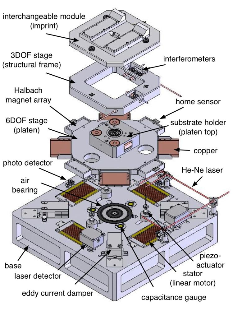
Precision motion stages are vital to the nano-manufacturing industry. The multi-DOF stage used in our research, Multi-Alignment and Positioning System (MAPS), was designed as a low cost, long range, flexible tool for nano-manufacturing. The multi-scale alignment and positioning system (MAPS) is composed of a 6 degree-of-freedom (DOF) wafer holder and a 3 DOF module holder, both of which move relative to the base. The module can be chosen for a desired task, such as atomic force microscopy, plasmonic lithography, or imprint lithography. (solid model by Ronnie Fesperman and Ozkan Ozturk at the University of North Carolina at Charlotte).
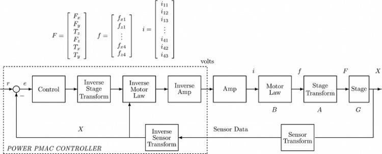
The MAPS stage is integrated with a Delta Tau Power PMAC real-time controller running on a 800MHz Power PC. Many features of the Power PMAC, such as trajectory generation, brushless motor commutation and phase finding, watchdog timer, built-in PID with feedforward, and a rugged compact chassis, reduce the development of control software and hardware needed for manufacturing tools. In addition, it is an option to write your own servo and phase alogorithms in C. The control algorithm receives the position estimate, calculated from the sensor data, \(X = [x\ y\ \theta_z\ z\ \theta_x\ \theta_y]^T\) and outputs a desired global force vector \(F = [F_x\ F_y\ T_z\ F_z\ T_x\ T_y]^T\). The global force vector is then transformed into the local motor forces \(f = [f_{x1}\ f_{z1}\ \dots\ f_{x4}\ f_{z4}]^T\) and finally must be converted into a current vector \(i = [i_{11}\ i_{12}\ i_{13}\ \dots\ i_{41}\ i_{42}\ i_{43}\ ]^T\) that will be supplied to the four linear motors. This process is reversed when applied to the platen. Feedback inputs enter the UMAC through 12-Bit AD’s for most of the sensors and 4096X SINCOS interpolators for the interferometers. Voltage outputs are sent to the amplifiers through the Power PMAC’s 16-Bit D/A’s. The Power PMAC’s default servo update is 442 microseconds while the phase update is 110 microseconds. See the control diagram below.